Popular Posts

Showing posts with label Windows. Show all posts

Friday, September 11, 2009

Download Thumbscrew : USB Write Blocker

Majority of the virus problem which we receive from the readers are those cases which infect the system through pen drives. According to our records about 40 percent of the total computer systems got virus or trojan infection through pen drives and USB portable devices like iPOd, Mp3 players etc.


Yesterday, I found a cool utility called Thumbscrew : USB Write Blocker , you can use this utility to disable writing to your USB drive. You can read full review about the utility here

lock

Let’s see how can you use this utility to protect your drive from viruses


Fix:

Thumbscrew is small handy utility which you can take any where on your pen drive use it to protect your pen drive from viruses on other computer systems by disabling Writing on that system. You can download thumbscrew here.


Follow the procedure below to protect your pen drive from viruses


1. In order to protect your pen drive from viruses you need to create a blank file named autorun.inf through notepad and place it in the root directory.

2. When you insert pen drive on any virus infected computer system it will throw a message that some thing is trying to copy and replace a file located in the root directory of your USB device and that is nothing but a virus.


Source :

http://www.troublefixers.com/disable-data-writing-on-your-usb-drive-to-protect-it-from-viruses/


How a virus in your pen drive infects?

We have received lot of problems where computers got infected easily by the viruses in the pen drives, pen drives have become one of the most easiest carriers of various types of viruses these days.

We will tell you how pen drives normally infect your computer systems and how can you open pen drive safely and back up your important data.

How a virus in your pen drive infects?

Most of the active viruses infect your windows system as soon as you double click on the Pen Drive icon in your my computer. As virus always creates a autorun.inf file which is a system ,hidden and a read only file on your pen drive. It point to the main virus file which is also located on the pen drive. When user double clicks on the pen drive files pointed by the autorun.inf got executed which copies the virus files on your system.

The image below shows the Autorun file entries in some special characters when you right click on the drive.

virus-pendrive

Let’s see how can you protect yourself by following certain practices.


Fix:

Let’s discuss these practices one by one:

1. Disable Autorun on Your Pen Drive:

  • Open to Start >> Run and type “gpedit.msc” (without quotes) and press enter. This will open Group policy editor.
  • Browse to Administrative templates >> System >> double click on Turn off Autoplay click on Enabled and Under Settings >> Select All Drives in the drop down and click OK (as shown in the image below)

disable-autoplay

2. Scan Your Pen Drive:

Whenever you insert your pen drive / portable drive into USB port on your system make sure to run a virus scan with your anti virus before opening your pen drive contents in windows explorer.

3. Use FreeCommander:

FreeCommander is again a file explorer like windows explorer, so you just need to download it by clicking here and install it.

After installing open your pen drive through FreeCommander (as shown in the image below)


freecommander-usbdrive-virus

Check if there are some additional files like autorun.inf , Funny UST Scandal.avi.exe ,Ravmon.exe ,New Folder.exe etc or any other file which you have not copied or created, delete all these suspicious files on your pen drive.

Source : http://www.troublefixers.com/how-to-protect-your-computer-from-virus-in-pen-drives/

Can not removely safely a pen drive ?

We attach portable USB device like pen drive, memory cards and portable drives etc. on our computer to transfer files from/to your computer.


When you try to remove a USB pen-drive by using “Safely Remove Hardware > Safely remove USB Mass Storage device” option, windows should stop all the read-write operations on the drive so that the drive can be removed.

But sometimes when you try to eject the USB device by using “Safely remove USB Mass Storage device” option, it shows a message box which says:

“The Device Generic volume cannot be stopped right now. Try stopping the device later”

problem-ejecting-usb-device

In such case its not safe to remove the pen drive as it can get corrupt or get damaged. Many of us face such problem in removing pen-drive. In this post we will see how to fix such issue.

Let’s see why it happens and the fix

Fix:

This error comes when you have an application which is running from your pen drive or may be some file or document opened from your pen-drive when you are removing your drive.

In short, some file on your pen drive is in use by some other program on that computer. So close all such files or applications and try removing the drive.

Pen Drive doesn’t show up as a drive icon in My Computer ?

You may have faced a problem when you insert your pen drive and it gets detected very easily but it doesn’t show up as a drive icon in My Computer. The computer detects the pen drive but data on pen drive is not visible as the pen drive is not visible in My Computer (Explorer).

This problem occurs mainly when windows XP fails to allocate a drive letter to your portable drive(pen drive). It occurs mostly with new pen drives connected to your computer for the first time. If you face such problem then it may not be the pen drive’s fault, rather it may be windows trouble.

Fix:

You can fix this issue by following some simple steps given below.

1. Click Start, click Run, type compmgmt.msc, and then click OK.

2. In the console tree, click Disk Management. The Disk Management window will appear.

3. On this disk management window, you can see some drives including the portable drive. Right click on your portable drive and click change drive letter and paths.

4. Now a assign a new drive letter which is not being used by any of your drives in My Computer.

5. After assigning the new drive letter your portable drive will show up in my computer with other drives

My computer does not detect pen drives and other USB devices like iPod or external hard drive

Fix:

In normal cases when you think your system is not detecting pen drives, it could be a case when your computer detects your pen drive but does not show up in my computer.

Method 1:

This could be due to no free drive letter has been assigned to your pen drive.

Method 2:

If none of your USB devices detect ,this could be due to wrong registry entries. i.e you need to delete UpperFilters and the LowerFilters registry values.

Method 2:

If none of your USB devices detect ,this could be due to wrong registry entries. i.e you need to delete UpperFilters and the LowerFilters registry values.


Follow the procedure listed below to correct your registry:

1. Open Start >> Run, and type "regedit" (without double quotes), and click OK.

2. Locate UpperFilters registry value. it resides in the following registry subkey:

HKEY_LOCAL_MACHINE\SYSTEM\CurrentControlSet\Control\Class\{4D36E980-E325-11CE-BFC1-08002BE10318}

3. Click on Edit menu, and select Delete and click OK.
Note: If you receive an error when you try to delete the registry subkey, you may not have correct permissions to edit the subkey.

4. Locate LowerFilters registry value. It resides in the following registry subkey:

HKEY_LOCAL_MACHINE\SYSTEM\CurrentControlSet\Control\Class\{4D36E967-E325-11CE-BFC1-08002BE10318}

5. Click on Edit menu, and select Delete and click OK.
6. Exit Registry Editor and restart your system.

Note : For all user, always be careful to work with registry values. If necessary take expert hands to solve this way.

Top 10 USB drive / pen drive related problems and fixes:

Top 10 USB drive / pen drive related problems and fixes:


Lets see a short summary of each problem and the fix:

Fix:

  1. Computer Does Not Detect Pen Drive or USB Drive or i-pod : This kind of problem is faced due to some bad registry settings. After you fix up the registry, the USB drive will work fine.
  2. Pen Drive or USB Mass storage device disabled at office or college or school: At many offices and colleges, the IT people disable or block the use of pen drives.
  3. Problem in removing pen drive: When you try to remove the pen drive via safely remove hardware option, it gives error “Generic volume can not be stopped right now”. It may damage your pen drive if it is removed without stopping it properly.
  4. Protect computer from virus in pen drive: Many of the deadly viruses spread easily through use of pen drive.
  5. USB drive is detected, but not shown in My Computer: This kind of problem is also seen in cases of conflict over drive letter assignment by windows. The drive is there and detected but without a valid drive letter assigned to it.
  6. Problem in formatting pen drive: Sometimes when you try to format the pen drive, you might see an error which says “Can not format the drive”. There can be several reasons for this.
  7. USB Device has Malfunctioned: This one of the unusual warnings which you get sometimes, the solutions to this problems sounds silly, but it works. See the solution in this blog later.
  8. Delayed Write failed error: This is another kind of error which is more common with USB hard drives due to some error in File allocation table. This problem can be fixed by following few simple steps.
  9. Disable data writing on pen drive: This is one of the articles which tells you how you can stop data writing on your pen drive on a particular computer. This will save the drive from getting virus infections.
  10. Fixed SATA Drive shown in removable USB drive list: This problem we have recently seen for many users. This is a kind for feature in a certain RAID configuration, but annoys many users.

Pen Drive Data Recovery Software : Download Demo

Pen Drive Memory stick data recovery software is safe easy and Non-Destructive Read-only removable USB drive Data retrieval software utility.

It is used to - restore recover and retrieve lost missing deleted formatted or corrupted Data files and folders from damaged Logically bad crashed memory stick usb thumb drive pen drive dongle external usb hard disk Drive or other usb removable disk drive. Software also includes support for compact flash memory card multimedia card SD card removable microdrive smart drive media flash card memory etc. Memory stick Data recovery Software recovers files and folders music pictures video digital image pictures photo images data file and directory and other data from your removable storage usb media including lost due to accidental deletion, format, corruption, Virus attack, damaged file system etc. Features:: * Ensures data recovery even from accidentally formatted removable media and Deleted files and folders. * Supports all type of usb drives and memory sticks including Apacer AVB Kingmax Lexar PenDrive PQI Ridata Supermedia Super Flash Transcend Apacer Kingston Sony generic Corsair PNY Simple Ritek Crucial Dane-Elec Viking SanDisk in all capacities e.g. 64MB 128MB 256MB 512MB 1GB 2GB 4GB etc * Data Retrieval Support for both type of formatting and Deletion either by Microsoft Windows or Apple Macintosh OSX. * Retrieve and Restore corrupted files and folders damaged due to human error or any Virus Generated Data Loss. * Recovers Data even if DRIVE NOT FORMATTED message is displayed by your Computer while accessing USB removable media in My Computer and usb device Volume is not Recognized by the System because file system is not detected. * Easiest Data retrieval software to restore lost data, recover formatted or damaged files before you fix and repair your corrupted storage device.

Download Demo Version from here ==>

or from here

Rapidshare Link

Sunday, July 26, 2009

Do I have to connect all 8 wires of a LAN cable ?

If you are using 100Base-T4 standards - that is you want to use cat 3, 4 or 5 cables ALL 4 PAIRS (8 wires) ARE REQUIRED. If you are using 100Base-TX (category 5 or 5e cables only) or 10Base-T the wires numbered 4 and 5 (one pair) and 7 and 8 (another pair) are not used in normal LAN operation but should still be connected since some equipment may use them for special purposes (we use them for power-over-ethernet in certain applications). They can be used for other functions e.g. telephony see above.

Beware:
You are taking a RISK that in the future some genius may invent a fantastic application for one or more of these pairs and you may have to re-wire. Whether you consider this a high or low risk is a personal decision.

What is category 5 (or Category 5e or Category 6) cabling

Category 5 UTP (Unshielded Twisted Pair) cable is defined by the EIA/TIA for use with 10 and 100 MB LANs (10baseT and 100baseT) as specification number EIA/TIA-568A. Category 5e is a slightly improved specification published as EIA/TIA-568A-A-5 . Category 6 is defined by EIA/TAI-568-B.2-1.

Hub vs Switch

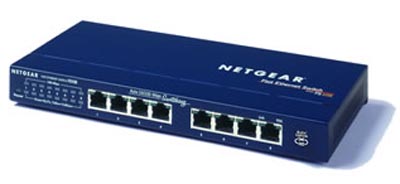
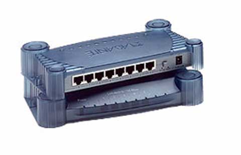
The price difference between a Switch and a Hub is almost vanishly small these days. Unless budget really is a key issue we would suggest a Switch. They come in all kinds of sizes 4, 5, 8, 16 and 24 ports. some have the ports at the back and leds at the front, others put both at the front.

RJ45 and LEDS at front

RJ45 at Rear LEDS at front

The general specification - irrespective of whether its a switch or hub - is:

  1. Minimum number of ports equal to the most systems you can think of connecting plus some (say 2) ('cos you are going to change your mind!)
  2. 10/100 Mbit/s auto sensing
  3. LINK LED for each port
  4. 10/100 LED for each port

They typically come with lots of other features e.g. Full/Half Duplex, managed or unmanaged - your budget will figure out what else you want or can afford.

Shielded Twisted Pair

Shielded Twisted Pair (STP) comes in a variety of formats. It is typically used in three applications:

  1. Where there is significant EMI in the environment such as caused by high-powered electric motors (elevator shafts), flourescent lighting etc. Additionally where there is significant Alien Crosstalk (ANEXT) such as in very high speed (gigabit and 10gb) LANs. In this case the ethernet signals in the cable are protected against external interference from either adjacent pairs or the environment.

  2. Where there is extremely sensitive electrical/electronic equipment in the surrounding environment or where security requirements demand elimination of eavesdropping possibilities from radiated LAN signals (TEMPEST). In this case the ethernet signals in the cable are contained and prevented from polluting, or escaping into, the external environment.

  3. Where maximum performance - either speed or distance - is required. As Ethernet speeds continue to increase either fiber or Shielded Twisted Pair is becoming increasingly common, for instance, to reach 100m distances at 10Gb speeds on copper will require shielded cable (limited to 55m for UTP).

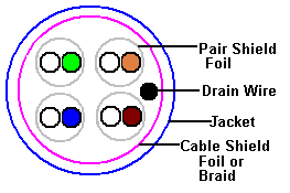
Shielded cable comes in three broad types with a confusing range of terminology:

  1. Where there is a single foil (FTP - Foil Twisted Pair) or braided (ScTP - Screened Twisted Pair) shield inside the jacket covering all four pairs.

  2. Where there is a foil shield covering each pair. This is frequently refered to as PiMF (Pairs in Metal Foil) and is designed primarily to eliminate Alien Cross-talk (ANEXT) from adjacent pairs.

  3. Where there is a foil shield covering each pair and a (Foil or Braided) shield covering the whaoe cable. This is frequently refered to as SSTP (Double Shield Twisted Pair) or even PiMF - since many manufacturers also add a jacket shield to foil covered pair cables.

In almost all cases there is a single ground wire (called a drain) which allows for connection to secondary grounding sources.

The diagram below illustrates the differences:

Shielded Twisted Pair

Notes:

  1. Shielded cable of any variety has a greater diameter than UTP and will therefore occupy more space in cable ducting and raceways.

  2. Connecting shielded cable is more complex and time consuming - but not execessively so - than conventional UTP. Manufacturers specifications vary enormously, expecially with respect to grounding, and should be followed closely.

  3. In shielded cable installations the jacks and receptacles are typically made of metal and the cable shield (foil or braid) is connected electrically to the connector and thence through the receptable to a suitable ground.

  4. Foil covered pairs are typically not connected to ground and thus provide only alien crosstalk immunity from adjacent pairs.

  5. Manufacturers specifications and measurements suggest that shielded cables do NOT create antenna effects - indeed experiments show that UTP creates a substantially greater antenna effect (~40db) over correctly grounded shielded cables.

  6. Even ungrounded shielded cables provide better performance (by ~20db) than conventional unshielded twisted pair (UTP).

  7. The drain wire provides a secondary or auxiliary ground method where metallic path grounding is provided by the connectors and, as such, is optional. In cases where metal connectors are not being used the drain wire may be used as the primary grounding method and needs to be routed independantly to a suitable ground.

RJ45 Connections - Some Basic Hints

  1. The RJ45 connector is the critical connection - always use the highest quality connectors you can afford. The most common cause of connection faults are bad connectors.

    There are different connectors for stranded and solid cable and manufacturers do not always do a good job at differentiating them. Spend the time to make sure you have the right connector type. If you use the wrong type of connector the cable may or may not work initially but it will almost certainly fail very quickly.

  2. Make and test practice cables until you get it right every time - especially before you destroy a cable you just spend 2 hours fitting.
  3. When cutting the exterior cover of the cable be very careful not to cut the insulation cover of the conductors since this can cause shorts - bottom line: the cable won't work.
  4. Expose a maximum of 1 inch of individual conductors when preparing the cable for connection.
  5. Line up all the conductors according to the wiring standard you are using.
  6. Measure the cable and trim the conductor ends so they are are all the same length and no individual conductor wire is visible outside the plastic cover of the RJ45 connector.
  7. Carefully slide the prepared cable into the RJ45 connector making sure the end of the conductors reaches the end of the RJ45 connector.
  8. Using the crimp tool make the connection using one firm squeeze operation.
  9. Test the cable before fitting if possible.

1000base-T Gigabit Ethernet

1000base-T is the copper based version of the gigabit Ethernet standard defined by 802.3ab which, since it is over 6 months old, is available free of charge from the enlightened IEEE. Great work. In passing, if you want to see sophistry raised to an art form read the EIA's justification for charging for their specifications. (Note: The original EIA statement is unfortunately no longer avilable on-line. This is a great loss to both the development of the English language in general, and comedy writing in particular.) The following notes apply to the 1000base-T spec:

  1. The standard defines auto-negotiation of speed between 10, 100 and 1000 Mbit/s so the speed will fall to the maximum supported by both ends - ensuring inter-working with existing installations.

  2. The cable specification base-line is ANSI/TIA/EIA-568-A-1995 (which you have to pay for). This means that if you know your cat5 cable was manufactured to this standard (there was a lower spec 1991 version of this specification) then it will support Gigabit Ethernet. Cat5 cable manufactured to the old specification may work or it may not - you need to run some tests. Cat5e and cat6 being higher spec cables will clearly support Gigabit Ethernet.

  3. Maximum runs are the standard 100m (~300ft).

  4. Gigabit Ethernet uses all 4 pairs (8 conductors). The transmission scheme is radically different (PAM-5 a 5 level amplitude modulation scheme) and each conductor is used for send and receive.

  5. Crossed Gigabit Ethernet cables must cross all 4 pairs.

100base-T Crossed cable (PC to PC or HUB to HUB)

Crossed cables are used to connect PCs to one other PC or to connect a HUB to a HUB. Crossed cable are sometimes called Crossover, Patch or Jumper cables. If your connection is PC to HUB you MUST use a Straight cable.

The following description shows the wiring at both ends (male RJ45 connectors) of the crossed cable. Note: The diagrams below shows crossing of all 4 pairs and allows for the use of cat3/4 cables with 100m LANs (100base-T4). Pairs 4,5 and 7,8 do not NEED to be crossed in 100base-TX wiring. See notes below.

crossed connection

We use RED for crossed cables (or more commonly now a red heat-shrink collar at each end).

NOTES:

  1. All our crossed wiring is now done to the 100base-T4 spec (uses all 4 pairs, 8 conductors) which you can use with 10base-T networks - but NOT necessarily the other way around.
  2. Many commercial 100m LAN cables seem not to cross pairs 4,5 and 7,8. If there is no cat3/4 wiring in the network this perfectly acceptable.
  3. Gigabit Ethernet uses all 4 pairs so requires the full 4 pair (8 conductor) cross configuration (shown above).
  4. If you are using Power-over-Ethernet (802.3af) then Mode A or Alternative A uses pairs 1,2 and 3,6 for both signals and power. Mode B or alternative B uses 4,5 and 7,8 to carry power. In all cases the spec calls for polarity insensitive implementation (using a diode bridge) and therefore crossing or not crossing pairs 4,5 and 7,8 will have no effect.

100base-T Straight Cable (PC to HUB/SWITCH)

Straight cables are used to connect PCs or other equipment to a HUB or Switch. If your connection is PC to PC or HUB to HUB you MUST use a Crossed cable.

The following cable description is for the wiring of BOTH ends (RJ45 Male connectors) with your category 5 wiring colors (TIA/EIA 568A or 568B though the example uses 568B colors).

Pin No. conductor color Name
1 white and orange TX_D1+
2 orange TX_D1-
3 white and green RX_D2+
4 blue BI_D3+ **
5 white and blue BI_D3- **
6 green RX_D2-
7 white and brown BI_D4+ **
8 brown BI_D4- **

We use BLUE for 100baseT straight cables.

NOTES:

  1. Wires marked ** are ABSOLUTELY NECESSARY for 100Base-T4 networks - used when any combination of category 3/4/5 cables are present, when using 1000base-T (GigE) and MAY be required for Power-over-Ethernet (PoE) - see below.

  2. Wires marked ** are not essential for 100Base-TX (using cat 5/5e ONLY cables) and CAN be used for other purposes, for example, telephony but, and our LAN plus Telephony article before you wire your entire neighbourhood for surround sound.

  3. The Power-over-Ethernet spec (802.3af) allows three schemes where power may be supplied. Two of these schemes use pairs 4,5 and 7,8 (marked ** in above table) for power (called Midspan PSE and Alternative B or Mode B), one scheme uses ONLY pairs 1,2 and 3,6 (Endpoint PSE, Alternative A or Mode A) for both signals and power. Depending on which scheme you use pairs 4,5 and 7,8 may be required.

  4. Gigabit Ethernet requires all 4 pairs (8 conductors).

  5. All our wiring is now done to the 100base-T4 spec which you can use with 10baseT networks - but NOT the other way around.

10baseT Crossed cable (PC to PC or HUB to HUB)

Crossed cables are used to connect PCs to one other PC or to connect a HUB to a HUB. Crossed cables are sometimes called Crossover, Patch or Jumper cables. If your connection is PC to HUB you MUST use a Straight cable.

The following description shows the wiring at both ends (male RJ45 connectors) of the crossed cable.

One end
RJ45 Male
Other end
RJ45 Male
1 3
2 6
3 1
4 * 5 *
5 * 4 *
6 2
7 * 8 *
8 * 7 *

NOTES:

  1. Items marked * are not necessary for 10M LANs but since you will be moving shortly to 100MB LANs (won't you) you will save yourself a LOT OF TIME finding crappy cable (that you made) that does not work. Instead we suggest you wire to 100BaseT standards.
  2. We use RED for crossed cables (or more commonly now a red heat-shrink collar at each end).
  3. All our crossed wiring is done to the 100base-T4 spec which you can use with 10baseT networks - but NOT always the other way around.

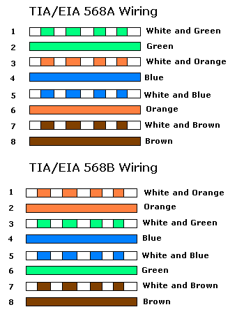
Category 5(e) (UTP) colour coding table

Category 5(e) (UTP) colour coding table

The following table shows the normal colour coding for category 5 cables (4 pair) based on the two standards supported by TIA/EIA.

These standards apply to the color code used within any SINGLE cable run - BOTH ENDS MUST USE THE SAME STANDARD. However, since they both use the same pinout at the connectors you can mix 568A and 568B cables in any installation.

cat colors

Crossed and Straight cables - when to use them

The following diagram shows the Normal use of Crossed and Straight cables (see also the notes below).


Notes:

1. We show Straight cables as BLUE and Crossed as RED. That is our convention. The cable color can be anything you choose or, more likely, the vendor decides.
2. To avoid the need for Crossed cables many vendors provide UPLINK ports on Hubs or Switches - these are specially designed to allow the use of a STRAIGHT cable when connecting back-to-back Hubs or Switches. Read the manufacturers documentation carefully.
3.

Increasingly vendor hubs (can you still buy them) and switches will auto-detect the connection type and internally switch the connectors so that STRAIGHT cables can be used everywhere.

up icon

Wednesday, April 22, 2009

Microsoft Word Shortcut Keys

Shortcut Keys Description
Ctrl + A Select all contents of the page.
Ctrl + B Bold highlighted selection.
Ctrl + C Copy selected text.
Ctrl + X Cut selected text.
Ctrl + P Open the print window.
Ctrl + F Open find box.
Ctrl + I Italic highlighted selection.
Ctrl + K Insert link.
Ctrl + U Underline highlighted selection.
Ctrl + V Paste.
Ctrl + Y Redo the last action performed.
Ctrl + Z Undo last action.
Ctrl + L

Aligns the line or selected text to the left of the screen.

Ctrl + E Aligns the line or selected text to the center of the screen.
Ctrl + R Aligns the line or selected text to the right of the screen.
Ctrl + M Indent the paragraph.
Ctrl + Shift + F Change the font.
Ctrl + Shift + > Increase selected font +1pts up to 12pt and then increases font +2pts.
Ctrl + ] Increase selected font +1pts.
Ctrl + Shift + < Decrease selected font -1pts if 12pt or lower, if above 12 decreases font by +2pt.
Ctrl + [ Decrease selected font -1pts.
Ctrl + Shift + * View or hide non printing characters.
Ctrl + Moves one word to the left.
Ctrl + Moves one word to the right.
Ctrl + Moves to the beginning of the line or paragraph.
Ctrl + Moves to the end of the paragraph.
Ctrl + Del Deletes word to right of cursor.
Ctrl + Backspace Deletes word to left of cursor.
Ctrl + End Moves the cursor to the end of the document.
Ctrl + Home Moves the cursor to the beginning of the document.
Ctrl + Spacebar Reset highlighted text to the default font.
Ctrl + 1 Single-space lines.
Ctrl + 2 Double-space lines.
Ctrl + 5 1.5-line spacing.
Ctrl + Alt + 1 Changes text to heading 1.
Ctrl + Alt + 2 Changes text to heading 2.
Ctrl + Alt + 3 Changes text to heading 3.
Ctrl + F1 Open the Task Pane.
F1 Open Help.
Alt + Ctrl + F2 Open new document.
Ctrl + F2 Display the print preview.
Shift + F3 Change the text in Microsoft Word from upper to lower case or a capital letter at the beginning of every word.
Shift + Insert Paste.
F4 Repeat the last action performed (Word 2000+)
F5 Open the find, replace, and go to window in Microsoft Word.
Ctrl + Shift + F6 Opens to another open Microsoft Word document.
F7 Spell and grammar check selected text and/or document.
Shift + F7 Runs a Thesaurus check on the word highlighted.
F12 Save as.
Shift + F12 Save.
Ctrl + Shift + F12 Prints the document.
Alt + Shift + D Insert the current date.
Alt + Shift + T Insert the current time.

Tuesday, April 21, 2009

Function Key : F12

  • Open the Save as window in Microsoft Word.
  • Shift + F12 save the Microsoft Word document.
  • Ctrl + Shift + F12 prints a document in Microsoft Word.

HOME : SHARE YOUR IDEAS